
Jul 27
/
Thanaris Thakornwarangkul
[LAB] MC-LAG with CSR1000v on MPLS L2VPN VPWS
เกริ่นก่อนละกัน สำหรับ LAB นี้ เราจะทำให้เร้าเตอร์ลูกค้า (CE) สามารถเชื่อมต่อไปหาเร้าเตอร์ของผู้ให้บริการ (PE) ทั้ง 2 ตัว โดยทำเป็น Multi-Chassis Link Aggregation (MC-LAG)
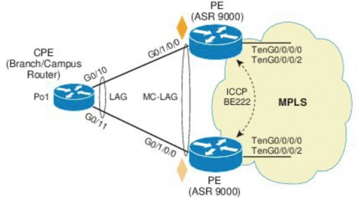
เราอาจจะเคยเห็นการใช้งาน Multi-Chassis Link Aggregation ลักษณะแบบนี้บน Network ทั่วไป ถ้าเป็นบน Catalyst Switch ก็จะเป็น Stack หรือ VSS ถ้าเป็นบน Nexus Switch จะเป็น vPC สามารถที่จะให้เราทำ Port-Channel หรือ Link Aggregation ข้าม Physical Switch ได้
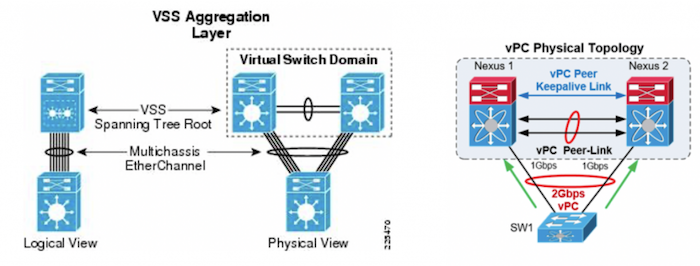
ซึ่งการใช้งานบน Service Provider เองก็สามารถทำลักษณะที่คล้ายกันได้ โดยฝั่งเร้าเตอร์ลูกค้า (CE) สามารถทีจะเชื่อมต่อไปหาเร้าเตอร์ของผู้ให้บริการ (PE) 2 ตัวได้ โดยให้บริการแบบ MPLS L2VPN จะใช้เป็น VPWS หรือ VPLS ก็ได้ เรียกว่า MC-LAG หรือ mLACP
มาดูคำศัพท์ที่ใช้กันก่อน
- Dual-Homed device (DHD) คือ อุปกรณ์ฝั่ง CE ที่เชื่อมต่อไปหา PE 2 ตัว (Dual-Hoomed) ที่รองรับ LACP
- Point of Attachment(POA) คือ อุปกรณ์ฝั่ง PE ที่เชื่อมต่อไปหา CE (DHD) โดยใช้งาน MC-LAG (mLACP)
- Inter-chassis Communication Protocol (ICCP) คือ protocol ที่ MC-LAG ใช้สำหรับ synchronized LACP stat ให้ POA คุยกันเพื่อสร้าง LACP peer ระหว่างกันเป็น redundant group เดียวกัน และทำให้ DHD มองเห็น POA ทั้ง 2 ตัวเป็นตัวเดียวกัน
Empty space, drag to resize
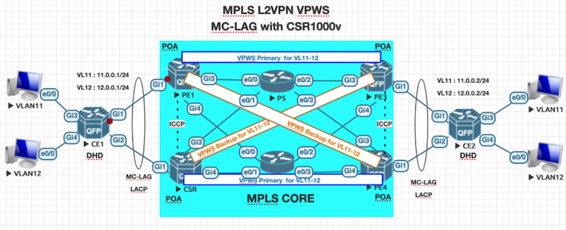
มาเริ่มคอนฟิกกันดีกว่า ใน LAB นี้ผมใช้ CSR1000v เป็นหลัก อาจจะไม่ได้ลงละเอียดหรืออธิบายทั้งคำสั่งนะครับ เพราะจะทำให้ยาวเกินไป
PE1 , PE2 , PE3 , PE4
อย่างแรกเลยคือเราต้อง enable OSPF ที่ PE1 , PE2 , PE3 , PE4 , P5 , P6 และ enable MPLS ให้เรียบร้อย
PE1 , PE2 , PE3 , PE4
router ospf 1
router-id x.x.x.x
network x.x.x.x 0.0.0.0 area 0
network 10.0.0.0 0.0.255.255 area 0
mpls ldp autoconfig
ปกติสามารถใช้คำสั่ง “mpls ip” บน interface เพื่อ enable mpls บน interface ได้ แต่สามารถใช้คำสั่ง “mpls ldp autoconfig” เพื่อ enables LDP บน interface ที่ enable IGP (support OSPF และ IS-IS)
mpls label protocol ldp
mpls ldp graceful-restart
mpls ldp session protection
mpls ldp discovery targeted-hello accept
เนื่องจาก PE ไม่ได้ต่อ direct connect กัน จึงต้องใช้ “targeted-hello” เพื่อให้ LDP เป็น neighbor กันได้ ไม่เช่นนั้นเดี๋ยวตอน config MC-LAG ระหว่าง POA จะทำให้ ICCP คุยกันไม่ได้
ต่อไปตั้งค่า VPWS และ MC-LAG ซึ่งตัว VPWS ก็ตาม Diagram เลย
PE1 (POA)
redundancy
interchassis group 100
monitor peer bfd
member ip 2.2.2.2
backbone interface GigabitEthernet3
backbone interface GigabitEthernet4
mlacp system-mac 0000.0000.000a
mlacp system-priority 1
mlacp node-id 1
!
pseudowire-class pw-primary
encapsulation mpls
status peer topology dual-homed
!
pseudowire-class pw-backup
encapsulation mpls
status peer topology dual-homed
!
interface Loopback0
ip address 1.1.1.1 255.255.255.255
!
interface Port-channel1
no ip address
load-interval 30
lacp failover non-revertive
lacp fast-switchover
lacp max-bundle 1
mlacp lag-priority 1
mlacp interchassis group 100
service instance 11 ethernet
encapsulation dot1q 11
xconnect 3.3.3.3 11 encapsulation mpls pw-class pw-primary
backup peer 4.4.4.4 11 pw-class pw-backup
!
service instance 12 ethernet
encapsulation dot1q 12
xconnect 3.3.3.3 12 encapsulation mpls pw-class pw-primary
backup peer 4.4.4.4 12 pw-class pw-backup
!
interface GigabitEthernet1
no ip address
lacp rate fast
channel-group 1 mode active
PE2 (POA)
redundancy
interchassis group 100
monitor peer bfd
member ip 1.1.1.1
backbone interface GigabitEthernet3
backbone interface GigabitEthernet4
mlacp system-mac 0000.0000.000a
mlacp system-priority 1
mlacp node-id 2
!
pseudowire-class pw-primary
encapsulation mpls
status peer topology dual-homed
!
pseudowire-class pw-backup
encapsulation mpls
status peer topology dual-homed
!
interface Loopback0
ip address 2.2.2.2 255.255.255.255
!
interface Port-channel1
no ip address
load-interval 30
lacp failover non-revertive
lacp fast-switchover
lacp max-bundle 1
mlacp lag-priority 2
mlacp interchassis group 100
service instance 11 ethernet
encapsulation dot1q 11
xconnect 4.4.4.4 11 encapsulation mpls pw-class pw-primary
backup peer 3.3.3.3 11 pw-class pw-backup
!
service instance 12 ethernet
encapsulation dot1q 12
xconnect 4.4.4.4 12 encapsulation mpls pw-class pw-primary
backup peer 3.3.3.3 12 pw-class pw-backup
!
interface GigabitEthernet1
no ip address
lacp rate fast
channel-group 1 mode active
PE3 (POA)
redundancy
interchassis group 100
monitor peer bfd
member ip 4.4.4.4
backbone interface GigabitEthernet3
backbone interface GigabitEthernet4
mlacp system-mac 0000.0000.000b
mlacp system-priority 1
mlacp node-id 1
!
pseudowire-class pw-primary
encapsulation mpls
status peer topology dual-homed
!
pseudowire-class pw-backup
encapsulation mpls
status peer topology dual-homed
!
interface Loopback0
ip address 3.3.3.3 255.255.255.255
!
interface Port-channel1
no ip address
load-interval 30
lacp failover non-revertive
lacp fast-switchover
lacp max-bundle 1
mlacp lag-priority 1
mlacp interchassis group 100
service instance 11 ethernet
encapsulation dot1q 11
xconnect 1.1.1.1 11 encapsulation mpls pw-class pw-primary
backup peer 2.2.2.2 11 pw-class pw-backup
!
service instance 12 ethernet
encapsulation dot1q 12
xconnect 1.1.1.1 12 encapsulation mpls pw-class pw-primary
backup peer 2.2.2.2 12 pw-class pw-backup
!
interface GigabitEthernet1
no ip address
lacp rate fast
channel-group 1 mode active
PE4 (POA)
redundancy
interchassis group 100
monitor peer bfd
member ip 3.3.3.3
backbone interface GigabitEthernet3
backbone interface GigabitEthernet4
mlacp system-mac 0000.0000.000b
mlacp system-priority 1
mlacp node-id 2
!
pseudowire-class pw-primary
encapsulation mpls
status peer topology dual-homed
!
pseudowire-class pw-backup
encapsulation mpls
status peer topology dual-homed
!
interface Loopback0
ip address 4.4.4.4 255.255.255.255
!
interface Port-channel1
no ip address
load-interval 30
lacp failover non-revertive
lacp fast-switchover
lacp max-bundle 1
mlacp lag-priority 2
mlacp interchassis group 100
service instance 11 ethernet
encapsulation dot1q 11
xconnect 2.2.2.2 11 encapsulation mpls pw-class pw-primary
backup peer 1.1.1.1 11 pw-class pw-backup
!
service instance 12 ethernet
encapsulation dot1q 12
xconnect 2.2.2.2 12 encapsulation mpls pw-class pw-primary
backup peer 1.1.1.1 12 pw-class pw-backup
!
interface GigabitEthernet1
no ip address
lacp rate fast
channel-group 1 mode active
CE1 (DHD)
interface Port-channel1
no ip address
lacp fast-switchover
!
interface Port-channel1.11
encapsulation dot1Q 11
ip address 11.0.0.1 255.255.255.0
!
interface Port-channel1.12
encapsulation dot1Q 12
ip address 12.0.0.1 255.255.255.0
!
interface GigabitEthernet1
no ip address
channel-group 1 mode active
!
interface GigabitEthernet2
no ip address
channel-group 1 mode active
CE2 (DHD)
interface Port-channel1
no ip address
lacp fast-switchover
!
interface Port-channel1.11
encapsulation dot1Q 11
ip address 11.0.0.2 255.255.255.0
!
interface Port-channel1.12
encapsulation dot1Q 12
ip address 12.0.0.2 255.255.255.0
!
interface GigabitEthernet1
no ip address
channel-group 1 mode active
!
interface GigabitEthernet2
no ip address
channel-group 1 mode active
มาตรวจสอบการทำงานกันครับ ซึ่งผมจะ show เฉพาะฝั่ง PE1 (POA Active) และ PE2 (POA Stabdby) นะครับ เพราะฝั่ง PE3 จะแสดงผลคล้ายกันกับ PE1 และ PE4 จะแสดงผลคล้ายกับ PE2
ตรวจสอบฝั่ง PE1 (POA) ที่เป็น Active (ฝั่ง PE3 ที่จะเห็นผลคล้ายกัน)
PE1#show mpls ldp iccp | i addr|state|event
rg_id: 100, peer addr: 2.2.2.2
iccp state: ICPM_ICCP_CONNECTED
app state: ICPM_APP_CONNECTED, ptcl ver: 0
app state: ICPM_APP_CONNECTED, ptcl ver: 0
rg_id: 100, peer addr: 2.2.2.2
iccp state: ICPM_ICCP_CONNECTED
app state: ICPM_APP_CONNECTED, ptcl ver: 0
app state: ICPM_APP_CONNECTED, ptcl ver: 0
peer addr: 2.2.2.2, ldp session: 0x5
ATS event occurred: TRUE
PE1#show redundancy interchassis
Redundancy Group 100 (0x64)
Applications connected: mLACP, Pseudo-mLACP
Monitor mode: BFD
member ip: 2.2.2.2 "PE2", CONNECTED
No BFD neighbor: Route available, BFD not started
mLACP state: CONNECTED
Pseudo-mLACP state: CONNECTED
backbone int GigabitEthernet3: UP (IP)
backbone int GigabitEthernet4: UP (IP)
ICRM fast-failure detection neighbor table
IP Address Status Type Next-hop IP Interface
========== ====== ==== =========== =========
2.2.2.2 UP RW 10.0.16.6 GigabitEthernet4
PE1#show lacp multi-chassis group
Interchassis Redundancy Group 100
Operational LACP Parameters:
RG State: Synchronized
System-Id: 1.0000.0000.000a
ICCP Version: 0
Backbone Uplink Status: Connected
Local Configuration:
Node-id: 1
System-Id: 1.0000.0000.000a
Peer Information:
State: Up
Node-id: 2
System-Id: 1.0000.0000.000a
ICCP Version: 0
State Flags: Active - A
Standby - S
Down - D
AdminDown - AD
Standby Reverting - SR
Unknown - U
mLACP Channel-groups
Channel State Priority Active Links Inactive Links
Group Local/Peer Local/Peer Local/Peer Local/Peer
1 A/S 1/2 1/1 0/0
PE1#show lacp internal
Flags: S - Device is requesting Slow LACPDUs
F - Device is requesting Fast LACPDUs
A - Device is in Active mode P - Device is in Passive mode
Channel group 1
LACP port Admin Oper Port Port
Port Flags State Priority Key Key Number State
Gi1 FA bndl-act 1 0x1 0x1 0x9001 0x3F
Peer (PE2) mLACP member links
Gi1 FA bndl-sby 2 0x1 0x1 0xA001 0xF
PE1#show mpls l2transport vc
Local intf Local circuit Dest address VC ID Status
------------- -------------------------- --------------- ---------- ----------
Po1 Eth VLAN 11 3.3.3.3 11 UP
Po1 Eth VLAN 12 3.3.3.3 12 UP
Po1 Eth VLAN 11 4.4.4.4 11 STANDBY
Po1 Eth VLAN 12 4.4.4.4 12 STANDBY
PE1#show xconnect all
Legend: XC ST=Xconnect State S1=Segment1 State S2=Segment2 State
UP=Up DN=Down AD=Admin Down IA=Inactive
SB=Standby HS=Hot Standby RV=Recovering NH=No Hardware
XC ST Segment 1 S1 Segment 2 S2
------+---------------------------------+--+---------------------------------+--
UP pri ac Po1:11(Eth VLAN) UP mpls 3.3.3.3:11 UP
IA sec ac Po1:11(Eth VLAN) UP mpls 4.4.4.4:11 SB
UP pri ac Po1:12(Eth VLAN) UP mpls 3.3.3.3:12 UP
IA sec ac Po1:12(Eth VLAN) UP mpls 4.4.4.4:12 SB
ตรวจสอบฝั่ง PE2 (POA) ที่เป็น Standby (ฝั่ง PE4 ที่จะเห็นผลคล้ายกัน)
PE2#show mpls ldp iccp | i addr|state|event
rg_id: 100, peer addr: 1.1.1.1
iccp state: ICPM_ICCP_CONNECTED
app state: ICPM_APP_CONNECTED, ptcl ver: 0
app state: ICPM_APP_CONNECTED, ptcl ver: 0
rg_id: 100, peer addr: 1.1.1.1
iccp state: ICPM_ICCP_CONNECTED
app state: ICPM_APP_CONNECTED, ptcl ver: 0
app state: ICPM_APP_CONNECTED, ptcl ver: 0
peer addr: 1.1.1.1, ldp session: 0x3
ATS event occurred: TRUE
PE2#show redundancy interchassis
Redundancy Group 100 (0x64)
Applications connected: mLACP, Pseudo-mLACP
Monitor mode: BFD
member ip: 1.1.1.1 "PE1^D", CONNECTED
No BFD neighbor: Route available, BFD not started
mLACP state: CONNECTED
Pseudo-mLACP state: CONNECTED
backbone int GigabitEthernet3: UP (IP)
backbone int GigabitEthernet4: UP (IP)
ICRM fast-failure detection neighbor table
IP Address Status Type Next-hop IP Interface
========== ====== ==== =========== =========
1.1.1.1 UP RW 10.0.26.6 GigabitEthernet4
PE2#show lacp multi-chassis group
Interchassis Redundancy Group 100
Operational LACP Parameters:
RG State: Synchronized
System-Id: 1.0000.0000.000a
ICCP Version: 0
Backbone Uplink Status: Connected
Local Configuration:
Node-id: 2
System-Id: 1.0000.0000.000a
Peer Information:
State: Up
Node-id: 1
System-Id: 1.0000.0000.000a
ICCP Version: 0
State Flags: Active - A
Standby - S
Down - D
AdminDown - AD
Standby Reverting - SR
Unknown - U
mLACP Channel-groups
Channel State Priority Active Links Inactive Links
Group Local/Peer Local/Peer Local/Peer Local/Peer
1 S/A 2/1 1/1 0/0
PE2#show lacp internal
Flags: S - Device is requesting Slow LACPDUs
F - Device is requesting Fast LACPDUs
A - Device is in Active mode P - Device is in Passive mode
Channel group 1
LACP port Admin Oper Port Port
Port Flags State Priority Key Key Number State
Gi1 FA bndl-sby 2 0x1 0x1 0xA001 0xF
Peer (PE1^D) mLACP member links
Gi1 FA bndl-act 1 0x1 0x1 0x9001 0x3F
PE2#show mpls l2transport vc
Local intf Local circuit Dest address VC ID Status
------------- -------------------------- --------------- ---------- ----------
Po1 Eth VLAN 11 3.3.3.3 11 STANDBY
Po1 Eth VLAN 12 3.3.3.3 12 STANDBY
Po1 Eth VLAN 11 4.4.4.4 11 STANDBY
Po1 Eth VLAN 12 4.4.4.4 12 STANDBY
PE2# show xconnect all
Legend: XC ST=Xconnect State S1=Segment1 State S2=Segment2 State
UP=Up DN=Down AD=Admin Down IA=Inactive
SB=Standby HS=Hot Standby RV=Recovering NH=No Hardware
XC ST Segment 1 S1 Segment 2 S2
------+---------------------------------+--+---------------------------------+--
IA pri ac Po1:11(Eth VLAN) UP mpls 4.4.4.4:11 SB
SB sec ac Po1:11(Eth VLAN) UP mpls 3.3.3.3:11 SB
IA pri ac Po1:12(Eth VLAN) UP mpls 4.4.4.4:12 SB
SB sec ac Po1:12(Eth VLAN) UP mpls 3.3.3.3:12 SB
มาดูฝั่ง CE1 (DHD) และลอง Ping เพื่อทดสอบส่งข้ามไปที่ CE2
CE1#show lacp internal
Flags: S - Device is requesting Slow LACPDUs
F - Device is requesting Fast LACPDUs
A - Device is in Active mode P - Device is in Passive mode
Channel group 1
LACP port Admin Oper Port Port
Port Flags State Priority Key Key Number State
Gi1 SA bndl 32768 0x1 0x1 0x1 0x3D
Gi2 FA susp 32768 0x1 0x1 0x1 0xF
CE1#ping 11.0.0.2
Type escape sequence to abort.
Sending 5, 100-byte ICMP Echos to 11.0.0.2, timeout is 2 seconds:
.!!!!
Success rate is 80 percent (4/5), round-trip min/avg/max = 2/7/23 ms
CE1#ping 12.0.0.2
Type escape sequence to abort.
Sending 5, 100-byte ICMP Echos to 12.0.0.2, timeout is 2 seconds:
.!!!!
Success rate is 80 percent (4/5), round-trip min/avg/max = 2/7/23 ms
มาลองทดสอบโดย down link ระหว่าง CE1 กับ PE1 (สีแดง)
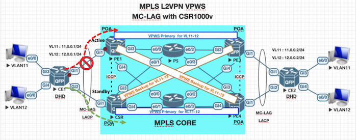
ทำการ Ping จาก CE1 ข้ามไปหา CE2 แล้วเดี๋ยวเราจะ shutdown แล้วดูกันกว่าจะเกิด timeout ไหม
CE1#ping 11.0.0.2 re 10000
Type escape sequence to abort.
Sending 10000, 100-byte ICMP Echos to 11.0.0.2, timeout is 2 seconds:
!!!!!!!!!!!!!!!!!!!!!!!!!!!!!!!!!!!!!!!!!!!!!!!!!!!!!!!!!!!!!!!!!!!!!!
!!!!!!!!!!!!!!!!!!!!!!!!!!!!!!!!!!!!!!!!!!!!!!!!!!!!!!!!!!!!!!!!!!!!!!
!!!!!!!!!!!!!!!!!!!!!!!!!!!!!!!!!!!!!!!!!!!!!!!!!!!!!!!!!!!!!!!!!!!!!!
ระหว่าง Ping ให้ทำการ shutdown link ระหว่าง CE1 และ PE1
PE1(config)#int gi1
PE1(config-if)#shutdown
กลับมาดูผล Ping หลังจาก link ระหว่าง CE1 และ PE1 down ลงไป สังเกตุว่าไม่มี downtime เลย
Sending 10000, 100-byte ICMP Echos to 11.0.0.2, timeout is 2 seconds:
!!!!!!!!!!!!!!!!!!!!!!!!!!!!!!!!!!!!!!!!!!!!!!!!!!!!!!!!!!!!!!!!!!!!!!
!!!!!!!!!!!!!!!!!!!!!!!!!!!!!!!!!!!!!!!!!!!!!!!!!!!!!!!!!!!!!!!!!!!!!!
!!!!!!!!!!!!!!!!!!!!!!!!!!!!!!!!!!!!!!!!!!!!!!!!!!!!!!!!!!!!!!!!!!!!!!
!!!!!!!!!!!!!!!!!!!!!!!!!!!!!!!!!!!!!!!!!!!!!!!!!!!!!!!!!!!!!!!!!!!!!!
!!!!!!!!!!!!!!!!!!!!!!!!!!!!!!!!!!!!!!!!!!!!!!!!!!!!!!!!!!!!!!!!!!!!!!
!!!!!!!!!!!!!!!!!!!!!!!!!!!!!!!!!!!!!!!!!!!!!!!!!!!!!!!!!!!!!!!!!!!!!!
ลองมาดูผล show ที่ CE1 , PE1 และ PE2 กันมั่งดีกว่า
สังเกตุที่ CE1 ไป forward ที่ Gi2 แทน หลังจากที่ Gi1 down ลงไป
CE1#show lacp internal
Flags: S - Device is requesting Slow LACPDUs
F - Device is requesting Fast LACPDUs
A - Device is in Active mode P - Device is in Passive mode
Channel group 1
LACP port Admin Oper Port Port
Port Flags State Priority Key Key Number State
Gi1 SA susp 32768 0x1 0x1 0x1 0x7D
Gi2 SA bndl 32768 0x1 0x1 0x1 0x3D
มาดูที่ PE1 ก็จะขึ้น State down ลงไปแล้ว
PE1#show lacp multi-chassis group
Interchassis Redundancy Group 100
Operational LACP Parameters:
RG State: Synchronized
System-Id: 1.0000.0000.000a
ICCP Version: 0
Backbone Uplink Status: Connected
Local Configuration:
Node-id: 1
System-Id: 1.0000.0000.000a
Peer Information:
State: Up
Node-id: 2
System-Id: 1.0000.0000.000a
ICCP Version: 0
State Flags: Active - A
Standby - S
Down - D
AdminDown - AD
Standby Reverting - SR
Unknown - U
mLACP Channel-groups
Channel State Priority Active Links Inactive Links
Group Local/Peer Local/Peer Local/Peer Local/Peer
1 D/A 3/2 0/1 1/0
PE1#show mpls l2transport vc
Local intf Local circuit Dest address VC ID Status
------------- -------------------------- --------------- ---------- ----------
Po1 Eth VLAN 11 3.3.3.3 11 DOWN
Po1 Eth VLAN 12 3.3.3.3 12 DOWN
Po1 Eth VLAN 11 4.4.4.4 11 DOWN
Po1 Eth VLAN 12 4.4.4.4 12 DOWN
มาลองดูที่ PE2 ก็จะขึ้นเป็น Active แทน
PE2#show lacp multi-chassis group
Interchassis Redundancy Group 100
Operational LACP Parameters:
RG State: Synchronized
System-Id: 1.0000.0000.000a
ICCP Version: 0
Backbone Uplink Status: Connected
Local Configuration:
Node-id: 2
System-Id: 1.0000.0000.000a
Peer Information:
State: Up
Node-id: 1
System-Id: 1.0000.0000.000a
ICCP Version: 0
State Flags: Active - A
Standby - S
Down - D
AdminDown - AD
Standby Reverting - SR
Unknown - U
mLACP Channel-groups
Channel State Priority Active Links Inactive Links
Group Local/Peer Local/Peer Local/Peer Local/Peer
1 A/D 2/3 1/0 0/1
จบไปเรียบร้อยครับสำหรับ MC-LAG อันนี้เป็นเพียงตัวอย่าง LAB เล็กๆให้เพียงได้เห็นภาพนะครับ จริงๆแล้วด้วยการทำงานและการตั้งค่า รวมถึง Restriction ต่างๆ มันมีเยอะเหมือนกัน ลองศึกษาเพิ่มเติมดูได้ครับ
- https://community.cisco.com/t5/service-providers-documents/asr9000-xr-multichassis-lag-or-mc-lag-mclag-guide/ta-p/3133825/page/8/show-comments/true#Checking_ICCP
- https://www.cisco.com/c/en/us/td/docs/ios-xml/ios/cether/configuration/15-s/ce-15-s-book/ce-multichass-lacp.html
สามารถดาวน์โหลดไฟล์ LAB ไปลองดูได้ครับ ใช้งานผ่าน EVE-NG
- https://drive.google.com/file/d/17PlhDkDuRZXZvRvNdxqIvydabIrjPUmU/view?usp=sharing
ให้ Import .zip file เข้าไปใน EVE-NG เลยนะครับ
ส่วน Image ตัว PE1/2/3/4 , CE1/2 ใช้ CSR1000v 16.x.x และ P5/6 ใช้ IOL ครับ ผมไม่ให้ตัว Image นะครับ สามารถลองหาดาวน์โหลดได้จากเว็บ Cisco.com
Thanaris thakornwarangkul (Nut)
Tripple Cisco CCIE #43646 | Huawei HCIP/HCSP | Aruba ACA/ACP-CA | CompTIA Security/Network
- Now I’m a Technical Solution Specialist with 15+ years experience in providing professional network consulting, implementation service to many leader companies in Thailand.
- 12 Years experience in technical trainer to new employee and clients. Freelance trainer in Cisco technology and certification
Plantecplus Co.,Ltd (NetPrime Training)
118/28 ถนน พระรามที่ 6 แขวงพญาไท เขตพญาไท กรุงเทพมหานคร 10400
โทร. 062-559-4622
อีเมล : netprime@plantecplus.com
118/28 ถนน พระรามที่ 6 แขวงพญาไท เขตพญาไท กรุงเทพมหานคร 10400
โทร. 062-559-4622
อีเมล : netprime@plantecplus.com
Copyright © 2022
เว็บไซต์เพิ่งย้ายระบบและทำการปรับปรุง
คอร์สที่เป็น Virtual Classroom และ Classroom ที่มีเอกสารอบรม ยังไม่เรียบร้อยดี กำลังอัพเดทค่ะ
Created with